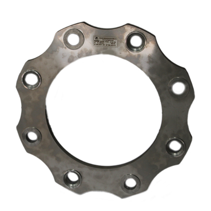
The purpose of JM single diaphragm coupling in mechanical equipment is to connect the driving part and the follower mechanism to rotate together and transfer energy and motion. It has no lubrication, long service life, and great compensation ability. It passes through the flexible steel sheet to transfer torque, with angular, axial, radial displacement compensation ability and damping effect. It uses elastic components or specific structures to adjust and compensate for the misalignment caused by production, installation and temperature changes, together with the general elastic coupling has the function of vibration isolation.

JM type single diaphragm coupling with its perfect function has become a hot topic in various areas of industry engineering research. The diaphragm in the coupling transmission is easy to assemble and disassemble, without lubrication, and can be ideal for various working conditions. Diaphragm coupling is favored by construction machinery and pressure extension machinery because of its high transmission efficiency. Although JM type single diaphragm coupling is durable, it will cause failure or even scrap due to various reasons, so it is of great significance to study its failure causes. Diaphragm failure is the primary form of coupling failure. When rotating up at high speed, when no torque is transferred, the floating outer tooth extraction sleeve needs to deviate from the operation under the action of centrifugal force, and the biased load needs to transfer enough torque to complete the stable operation. Because the tip positioning is generally small, the lifting of the external gear sleeve can be biased less, the centrifugal force is small, and the required torque for stable operation is small.

JM type single diaphragm coupling under normal working conditions, the torque transmitted will be much larger than the small force required for R constant operation, and after transferring the torque, it can finish self-centering and reach stable operation. The connecting shaft of buoyancy is planned into a hollow shaft to reduce weight and improve the stability of buoyancy parts. The gear teeth are positioned at the top of the tooth to reduce the top clearance. Dynamic balancing accuracy requires the improvement of action balance by separating the output shaft and gas turbine rotating shaft installed in the accessory gear box.
Contact: Spark Wang
Phone: 86-19932127135
E-mail: admin@rongxingcoupling.com
Add: North side of Planning 4th Road, Southern Industrial New Town, Jizhou District, Hengshui City, Hebei Province, China