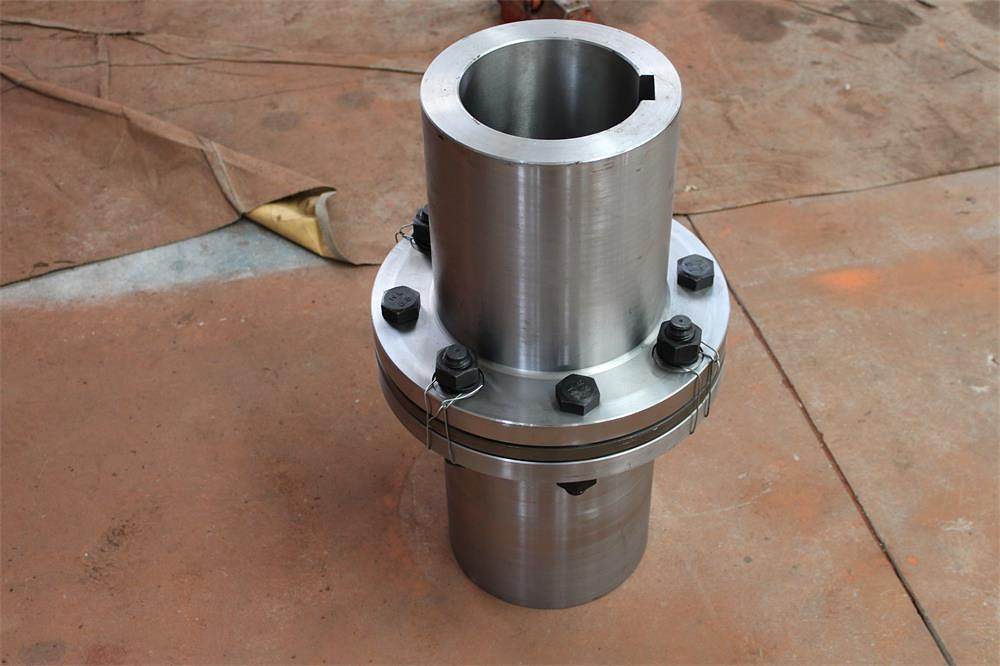
Introduction to the main characteristics of diaphragm coupling:
1. It has strong ability to compensate for misalignment of two axes. Compared with gear couplings, the angular displacement
can be doubled. The reaction force during radial displacement is small and the flexibility is large. It allows certain axial, radial
and angular displacements. Displacement.
2. Adapt to working in high temperatures (-80+300) and harsh environments, and can move safely under conditions of shock
and vibration.
3. It has obvious shock absorption effect, no noise and no wear.
4. High transmission efficiency, up to 99.86%. Especially suitable for medium and high speed high power transmission.
5. Simple structure, light weight, small size, and easy to assemble and disassemble. It can be assembled and disassembled
without moving the machine (referring to the type with intermediate shaft), and no lubrication is required.
6. It can accurately transmit the speed and operate without slip. It can be used for the transmission of precision machinery.
Various problems will occur during the installation process of diaphragm couplings. How should we judge if we encounter
them during installation?
The following are the issues that should be paid attention to before installing the diaphragm coupling:
(1) Dynamic balancing.
As the machine speed increases, there is an eccentricity between the inertia spindle of any rotating component and the
rotation axis. The unbalanced inertia moment it generates during operation will definitely cause vibration of the
transmission shaft system, leading to machine component failure. If there are parts in the elastic coupling that can move
relative to each other, it is more likely to cause imbalance. Therefore, the diaphragm coupling itself in many high-speed
equipment has been dynamically balanced, and the half coupling is installed on the shaft and then dynamically balanced
to ensure the dynamic balance of the system.
For the unit, when maintenance and technical personnel pay more attention to it, the installation of the coupling will
generally be carried out according to the design requirements. But for high-speed pumps, it is easy for maintenance
personnel to ignore the balance problem of the wheel. Compared with the mass of the high-speed pump rotor, the
counterwheel accounts for a large proportion, and it is easy to produce a large unbalanced force at high speeds. The input
shaft of a high-speed pump is subject to relatively complex forces, and unbalanced forces can easily interfere with the
normal forces of the bearings and gears, causing equipment abnormalities. Therefore, it is recommended that when installing
the diaphragm coupling, the installation should be strictly in accordance with the design requirements to ensure the normal
operation of the equipment.
(2) Deformation of half coupling.
Improper use or installation may cause deformation of the half coupling, which will cause the diaphragm to produce an
abnormal bending stress when installing the tightening bolts. Different from the aforementioned additional stress caused by
axial deviation, this bending stress is asymmetric to the diaphragm and occurs at the deformation part. The size of the
bending stress and the degree of deformation, the thickness of the diaphragm, the number of bolts, the radius of the bolts,
etc. related factors. Deformation of the half coupling can easily cause vibration, noise, premature cracking of the diaphragm,
etc.
During maintenance, there are too few inspections for the deformation of the half coupling. According to relevant
manufacturer information, generally the runout of the outer circle and end face of a diaphragm half coupling is ≤0.05mm, and
the limit runout of a diameter >250mm or a tapered hole fit is ≤0.08mm. Therefore, it is recommended to determine the
maintenance procedures and check the deformation of the half coupling during installation to ensure that the equipment
operates normally.

(3) Installation
The axis of the diaphragm coupling is crooked and the coupling cannot be bumped in: In order to prevent this type of
accident, in addition to being correct in calibrating the axis, the position of the coupling hole and the shaft, and the
position of the collision block, attention must also be paid to , The location of the impact point should be selected well,
the first and second blows should be light, and only after a certain distance (about 1/3) has been reached, can the
forceful blow be used.
(4) Others
Some other minor issues should also be noted: the coupling mounting bolts cannot be replaced with ordinary bolts. The
mounting bolts should be tightened to the required torque. The bolt penetration direction cannot be reversed. If the
diaphragm has pre-stretching or pre-compression requirements, be sure to determine the starting position between the prime
mover and the equipment, and then add or subtract the adjusting gasket on the coupling as required. The coupling and the
shaft are matched with a tapered hole. Be sure to check the contact rate of the inner hole.
Contact: Spark Wang
Phone: 86-19932127135
E-mail: admin@rongxingcoupling.com
Add: North side of Planning 4th Road, Southern Industrial New Town, Jizhou District, Hengshui City, Hebei Province, China